LEDs Adressables
NeoPixel + Arduino
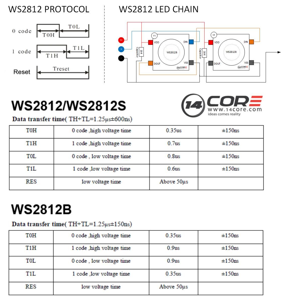
WS2811
WS2812[B]
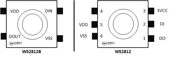
Connexions aux micro-contrôleurs
Source : Adafruit

When connecting NeoPixels to any LIVE power source or microcontroller, ALWAYS CONNECT GROUND (–) BEFORE ANYTHING ELSE. Conversely, disconnect ground last when separating.
When using a DC power supply, or an especially large battery, we recommend adding a large capacitor (100 to 1000 µF, 6.3V or higher) across the + and – terminals. This prevents the initial onrush of current from damaging the pixels. See the photo on the next page for an example.
With through-hole NeoPixels (5mm or 8mm round), add a 0.1 µF capacitor between the + and – pins of EACH PIXEL. Individual pixels may misbehave without this “decoupling cap.” Strips and boards have these caps built-in.
Adding a ~470 ohm resistor between your microcontroller's data pin and the data input on the NeoPixels can help prevent spikes on the data line that can damage your first pixel. Please add one between your micro and NeoPixels! Our NeoPixel rings already have this resistor on there
Matrices
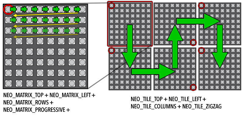
- Les matrices sont en fait des chaînes de LEDs (NeoPixels) rangées en carrés
- Arrangements des LEDs
- Chaque ligne ou colonne complète la précédente en repartant du début = « PROGRESSIVE »
- Les lignes / colonnes s'enchaînent du début à la fin puis de la fin au début = « ZIGZAG »
- Dans le code on indique dans quel coin est la première LED, puis l'arrangement, puis le type de LED
- On peut aussi indiquer si c'est une matrice de matrices (pour faire un truc immense !)
Arrangements des LEDs
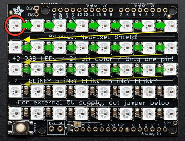
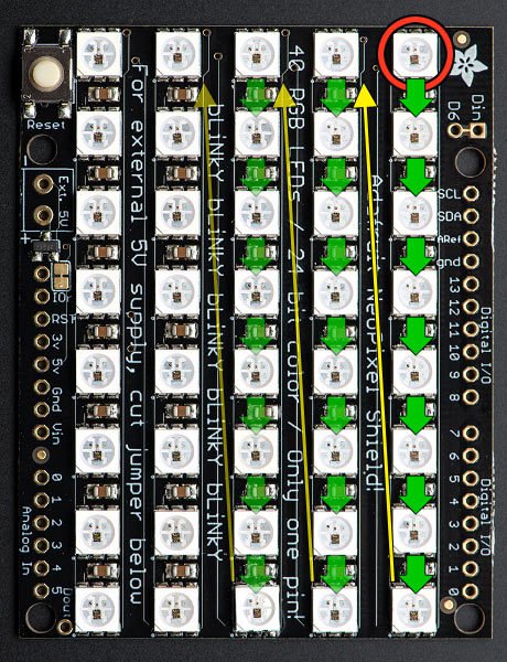
Code d'initalisation de la matrice de LEDs
/**
The first two arguments — 5 and 8 — are the width and height of the matrix, in pixels. The third argument — 6 — is the pin number to which the NeoPixels are connected. On the shield this is hard-wired to digital pin 6, but standalone matrices are free to use other pins.

The next argument is the interesting one. This indicates where the first pixel in the matrix is positioned and the arrangement of rows or columns. The first pixel must be at one of the four corners; which corner is indicated by adding either NEO_MATRIX_TOP or NEO_MATRIX_BOTTOM to either NEO_MATRIX_LEFT or NEO_MATRIX_RIGHT. The row/column arrangement is indicated by further adding either NEO_MATRIX_COLUMNS or NEO_MATRIX_ROWS to either NEO_MATRIX_PROGRESSIVE or NEO_MATRIX_ZIGZAG. These values are all added to form a single value as in the above code.

NEO_MATRIX_TOP + NEO_MATRIX_RIGHT + NEO_MATRIX_COLUMNS + NEO_MATRIX_PROGRESSIVE

The last argument is exactly the same as with the NeoPixel library, indicating the type of LED pixels being used. In the majority of cases with the latest NeoPixel products, you can simply leave this argument off…the example code is just being extra descriptive.

The point of this setup is that the rest of the sketch never needs to think about the layout of the matrix. Coordinate (0,0) for drawing graphics will always be at the top-left, regardless of the actual position of the first NeoPixel.
*/

Adafruit_NeoMatrix matrix = Adafruit_NeoMatrix(5, 8, 6,
  NEO_MATRIX_TOP     + NEO_MATRIX_RIGHT +
  NEO_MATRIX_COLUMNS + NEO_MATRIX_PROGRESSIVE,
  NEO_GRB            + NEO_KHZ800);