Outils pour utilisateurs
Ceci est une ancienne révision du document !
Voltmètre / Ampèremètre INA219


SPECS & FEATURES
- Operational Voltage (3 – 5.5 Volts): The INA219 operates between 3 to 5.5 volts, increasing its compatibility with various systems running at either 3.3V or 5V logic level. This feature enhances the module’s flexibility in diverse circuit designs.
- Bus Voltage Range (0 – 26 Volts): The INA219 can monitor power supplies within 0 to 26 volts range. This broad range makes the module applicable to low-voltage logic circuits and higher-voltage power supplies.
- Current Sensing Range (±3.2A with ±0.8mA resolution): The INA219 can monitor a current range of ±3.2A with a precise resolution of ±0.8mA. This capacity makes it suitable for various applications including power management, battery chargers, and DC motor control, enabling accurate tracking and control of power consumption.
- 0.1 ohm 1% 2W Current Sense Resistor: The module uses a 0.1-ohm shunt resistor with a 1% tolerance and 2W power rating for current sensing. The low resistance value minimizes power loss, while the 1% tolerance ensures measurement accuracy. The 2W power rating indicates its robustness, supporting current measurements up to ±3.2A.
I2C
I2C Address
The INA219 uses the I2C protocol to communicate with microcontrollers, and each device on the I2C bus must have a unique address. The default I2C address for the INA219 is 0x40 (or 1000000 in binary).
The address can be changed if you want to use multiple INA219 sensors on the same I2C bus. The INA219 allows up to 16 different I2C addresses, ranging from 0x40 to 0x4F. This is achieved by configuring the states of the two address pins A0 and A1. On the INA219 module, these two pins, A0 and A1, are often found with solder pads or jumpers. By default, they are connected to the Ground (GND) which corresponds to the default address 0x40.
| A1 | A0 | Slave Address (Hex) |
|---|---|---|
| GND | GND | 0x40 |
| GND | 0x41 | |
| GND | SDA | 0x42 |
| GND | SCL | 0x43 |
| GND | 0x44 | |
| 0x45 | ||
| SDA | 0x46 | |
| SCL | 0x47 | |
| SDA | GND | 0x48 |
| SDA | 0x49 | |
| SDA | SDA | 0x4A |
| SDA | SCL | 0x4B |
| SCL | GND | 0x4C |
| SCL | 0x4D | |
| SCL | SDA | 0x4E |
| SCL | SCL | 0x4F |
You can change the I2C address by changing the connections of these pins to either GND, SDA, SCL, or leaving them floating (not connected). For instance, if you connect the A0 pin to SDA and A1 to GND, the address will be 0x48.
So, if you want to have multiple INA219 modules in the same system, you just need to set a unique address for each one by configuring the A0 and A1 pins accordingly. Remember, any time you change the I2C address, you must update the address in your microcontroller’s software so it knows where to find each INA219 on the I2C bus.
REGISTERS & VALUES CALCULATIONS
The INA219 has a set of internal registers that hold measurement data and control settings. They can be accessed via the I2C interface to configure the chip, initiate measurements, and read measurement results.
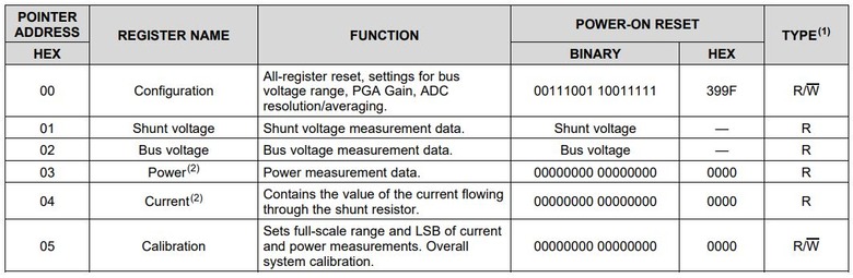
Configuration Register (Address = 00h)
This register is used to control various aspects of the INA219, such as the bus voltage range, PGA gain, ADC resolution/averaging, operating mode, and more. It can be read or written to configure the INA219 as needed.
Shunt Voltage Register (Address = 01h)
This register holds the raw measurement result for the shunt voltage. It can be read to obtain the shunt voltage measurement, and the value must be processed as per the datasheet’s guidance to get the actual voltage in volts.
Shunt voltage (in volts) is calculated by taking the raw reading from the Shunt Voltage Register and multiplying it by 10 µV. The formula is:
Shunt Voltage (V) = Shunt Voltage Register Value * 10 µV
Bus Voltage Register (Address = 02h)
This register holds the raw measurement result for the bus voltage. It can be read to obtain the bus voltage measurement, and the value must be processed as per the datasheet’s guidance to get the actual voltage in volts.
Bus voltage (in volts) is calculated by taking the raw reading from the Bus Voltage Register and multiplying it by 4 mV. The formula is:
Bus Voltage (V) = Bus Voltage Register Value * 4 mV
Power Register (Address = 03h)
This register holds the calculated power value. It can be read to obtain the power measurement, and the value must be processed as per the datasheet’s guidance to get the actual power in watts.
Power (in watts) is calculated by taking the raw reading from the Power Register and multiplying it by the Power_LSB value (defined when the calibration register is set). The formula is:
Power (W) = Power Register Value * Power_LSB
Current Register (Address = 04h)
This register holds the calculated current value. It can be read to obtain the current measurement, and the value must be processed as per the datasheet’s guidance to get the actual current in amperes.
Current (in amperes) is calculated by taking the raw reading from the Current Register and multiplying it by the Current_LSB value (defined when the calibration register is set). The formula is:
Current (A) = Current Register Value * Current_LSB
Calibration Register (Address = 05h)
This register is used to set the calibration value for the current and power calculations. It can be read or written to set the correct calibration value.
WIRING
PINOUT
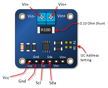
- VCC this pin is used to supply the operating voltage to the INA219 module. It can handle an input voltage of 3.3V to 5.5V.
- GND this is the Ground pin.
- SCL this pin is used for the clock line of the I2C interface.
- SDA this pin is used for the data line of the I2C interface.
- Vin- this pin connects to the negative terminal of the voltage supply that you want to measure. This pin is also where the shunt resistor is placed and is used for current sensing.
- Vin+ this pin connects to the positive terminal of the voltage supply that you want to measure.
Librairie(s)
DATASHEET
ARDUINO CODE
#include <Wire.h>
#include <Adafruit_INA219.h>

Adafruit_INA219 ina219;

void setup(void)
{
  Serial.begin(9600);
  while (!Serial)
  {
    delay(1);
  }

  // Initialize the INA219.
  if (! ina219.begin())
  {
    Serial.println("Failed to find INA219 chip");
    while (1)
    {
      delay(10);
    }
  }
  // To use a slightly lower 32V, 1A range (higher precision on amps):
  //ina219.setCalibration_32V_1A();
  // Or to use a lower 16V, 400mA range, call:
  //ina219.setCalibration_16V_400mA();

  Serial.println("Measuring voltage, current, and power with INA219 ...");
}

void loop(void)
{
  float shuntvoltage = 0;
  float busvoltage = 0;
  float current_mA = 0;
  float loadvoltage = 0;
  float power_mW = 0;

  shuntvoltage = ina219.getShuntVoltage_mV();
  busvoltage = ina219.getBusVoltage_V();
  current_mA = ina219.getCurrent_mA();
  power_mW = ina219.getPower_mW();
  loadvoltage = busvoltage + (shuntvoltage / 1000);

  Serial.print("Bus Voltage:   "); Serial.print(busvoltage); Serial.println(" V");
  Serial.print("Shunt Voltage: "); Serial.print(shuntvoltage); Serial.println(" mV");
  Serial.print("Load Voltage:  "); Serial.print(loadvoltage); Serial.println(" V");
  Serial.print("Current:       "); Serial.print(current_mA); Serial.println(" mA");
  Serial.print("Power:         "); Serial.print(power_mW); Serial.println(" mW");
  Serial.println("");

  delay(1000);
}
Outils de la page
