Outils pour utilisateurs
KENWOOD TM-733E
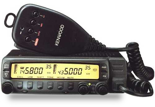
KENWOOD TM-733E
DOCUMENTATION
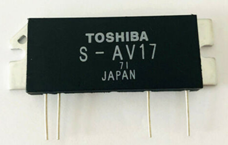
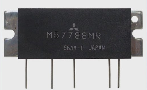
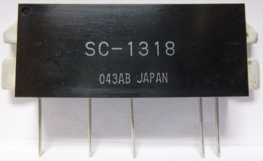
VHF HYBRID MODULES
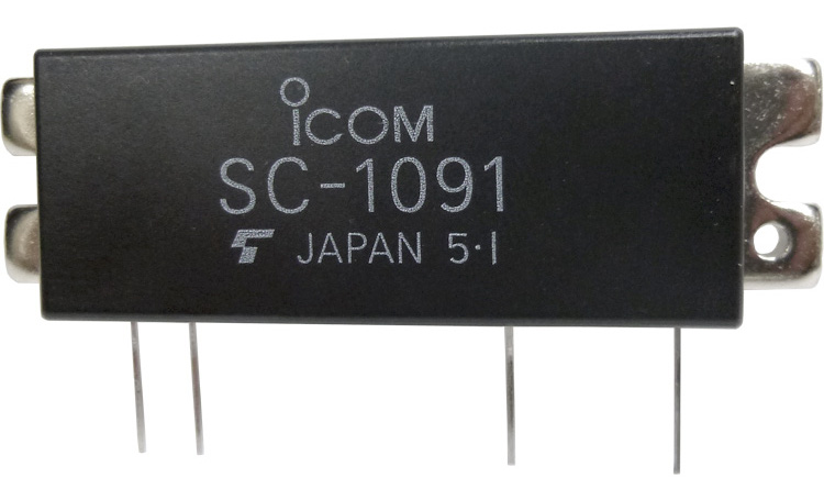
UHF HYBRID MODULES
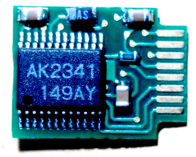
TSU-8 CTCSS DECODER MODULE (OPTIONAL)
DISPLAY BACK LIGHT REPLACEMENT
UNDOCUMENTED INFOS
Scott, here is the new release of TM733A.DOC. You can also delete the
TM733.MOD file from /pub/hamradio/mods/kenwood because all the info in the
.MOD file is in the .DOC file, but in a more updated and specific format.
Thanks for the great ham radio ftp site.
--
Brad A. Killebrew N5LJV, EMT-B | Student of Computer Engr Technology
President, University of Houston ARC | University of Houston, Texas
Internet: n5ljv@uh.edu | U of H Amateur Radio Club WB5FND
AMPRnet : n5ljv@sugarland.ampr.org | uharc@post-office.uh.edu
Packet : n5ljv@f6cnb.#setx.tx.usa.na | Box 85-T2, 4800 Calhoun, 77204-4083
AT&Tnet : 713-743-6676 Fax 743-4032 | For info, finger tech14c@jetson.uh.edu
-------------------------------- TM733.DOC ----------------------------------
Modifications, Undocumented Features, and Bugs for the Kenwood TM-733A.
Release 2.0 Updated October 1, 1994
Updates for Release 2.0 are identified by parenthetical statements.
There is also some new information sprinkled throughout the previous material
either to update it, to correct misinformation, or to be more specific.
This document is a compilation of Internet messages from
Steve Haehnichen KE6JGK and Brad Killebrew N5LJV, edited by Brad Killebrew.
------------------------------
Extended RF Modifications
------------------------------
Refer to diagram below. (Inserted into Release 2.0)
Remove power source from the radio.
Remove the display panel.
Remove the top cover the radio.
Face the front of the radio away from you.
Remove the speaker.
Looking from the back of the radio, the control board is vertically
mounted just behind the front panel wall (which can be removed easily
if better access is needed.)
Just to the right of a chip labeled XRU4066BCF and just to the left of
two green wires (B2 & B3 which are draped over the board to the rear) are
two zero-ohm SMT resistors, B0 and B1, marked "000".
Remove B0. (the one on the left - furthest from the green wires)
Taking it out might be a bit tricky. It's glued down for surface-mount
assembly. Be careful not to pull the trace from the board.
Perform a CPU reset by holding [MR] while turning on the radio.
It will then ask if it is "OK?" to reset, press [MR] again.
The ranges after modification are as follows:
Tx: 136-174 410-470
Rx: 118-174 300-470
The cellular band is indeed missing.
ONLY Removing Jumper 1 (B2) is the MARS/CAP modification.
** Diagram of specified area on Control Board **
EDGE OF BOARD, viewed from the rear, looking toward front panel
Green jumper wires (B2, B3)
_______ ___ ___ ___ ___ ___
-| |- | _ | | _ | |_ _| |_ _| |___|
-| XRU |- B0| | B1| | B2 | B3 |
-| 4066BF|- |_| |_| _|_ _|_ ___
-| |- |___| |___| |___| |___| |___|
-| |- _______
-| |- -| |-
-|_______|- -| |-
-| |-
-| |-
-| |-
-| |-
-|_______|-
The jumpers are actually soldered on the other side of the board,
but the loops come up over the top and hang over the B0/B1 side.
B0=R414
B1=R412
Here's something interesting! According the Kenwood rep I spoke to,
performing this mod *does not* void your factory warranty. The same
goes for any Kenwood published service bulletin or modification info.
We are encouraged to perform the repairs ourselves to save them the
trouble and expence.
------------------------------
DTMF Remote via Microphone
------------------------------
The TM-733 is fully DTMF remotable via the microphone (documented).
The radio can also be externally DTMF controllable with an HT, but that
will be described later.
The DTMF control keys are exactly as shown on page 81 of the
manual. Note that the microphone is active all the time, so any
ambient DTMF tones near your mic will also change rig settings. This
includes tones coming in on the other band and out the speaker.
------------------------------
Cross Band Repeating
------------------------------
Cross band repeat isn't documented but comes ready from the factory.
To enable cross band repeat from the front panel, first select a band
by pressing BAND SELECT. Then, change the control to the other band by
hitting [CONT SEL]. Next, press [F] for one second, then the "X" button
(far right side). Decimals will appear between the Kilohertz digits, and
the "ON" indicator will light momentarily. The microphone sequence to
enable cross band repeat while in remote control mode is "DC".
The transmitter hang time can be toggled between 500ms to 0ms by
turning on the radio with [LOW] pressed. They also recommend enabling
the Time-out Timer, for obvious reasons.
Note that the TM-733 can also be used as a "one-way" cross-band repeater.
For example, if you can receive a distant repeater with your HT, but have
difficulty getting into it, you can use the TM-733 to boost your transmitted
signal. To set this up, just omit the part where you "change the control
to the other band by pressing [CONT SEL]." Doing this will setup the TM-733
to repeat your signal to the other band, but will not retransmit the distant
station back to you. If this sounds ambiguous, play around with it a little
and it will begin to make sense.
------------------------------
DTMF Paging and Squelch
------------------------------
The DTMF Paging & DTMF Squelch protocol (AAA*BBB) is compatible with
the Yaesu 530 and all Kenwood radios supporting this.
------------------------------
DTMF Monitor
------------------------------
There are some serious bugs in the "DTMF Monitor" feature (Page 63:
[PTT] + [DWN] + Power On). This feature supposedly lets you hear the
DTMF tones you are transmitting. The first problem is that it only
gives you a short tone from the internal speaker. This is not true to
the transmitted tone that lasts as long as you hold the key. The much
bigger problem is that it mixes the desired tone and the feedback tone
resulting in an almost indecodable DTMF tone. Kenwood is aware of this bug.
(Updated information for Release 2.0):
Per Ricardo, a Kenwood technician, they are aware of this bug and are
working on a fix. No details yet.
------------------------------
Front Panel
------------------------------
There are two undocumented icons on the display; one is the "heart"
symbol. Anyone know what that's for? It could just be a spare. I
noticed they used the odd "spade" symbol to indicate AM receive, so
maybe these were last minute extras. Dunno..
From looking at the schematic, it seems that the only programmable
memory is physically located in the detachable front-panel. I think
this means that if I use my front-panel on someone else's radio, I get
all my memories and settings. Anyone try this?
The whole front panel is connected to the rig by four wires (yep,
including the volume/squelch pots.) According to the schematic, these
are: power, ground, data in, and data out. I'm wondering how hard it
would be to make a PC interface for this thing and replace the whole
display and controls with a full-screen version. It wouldn't surprise
me if many of the programming limits were also imposed by the
front panel, and not the unit.
------------------------------
Wireless Cloning
------------------------------
The advertised but undocumented Wireless Clone function is described
in App Note AAN-0008 which they will mail out on request. (Maybe if
enough people ask for it, they will include all the functions in
future instruction manuals.) In summary:
- Prepare the two radios for simplex operation on the same frequency.
- Turn both radios off
- Press [CALL]+[SHIFT] + [Pwr On].
- This should place the radios is clone mode with "CLonE" on the display.
- Press PTT on the "Master" radio momentarily. This will start
sending the programming DTMF tones.
- After all data has been transferred, the display of all radios will
read "End", indicating success.
- If the signal is interrupted or corrupted, the "Slave" displays will
read "Err". Turn them off and try again.
Notes:
- Both the Master and Slave radios must have the same number of
memory channels available for each band. Example: You can not clone a
stock Master to a Slave with ME-1 memory expansion.
- You can not clone between different Kenwood radio models, even if
they seem identical.
Be careful when using the clone feature. It has been known to wipe out
or scramble memories on the master radio during or right after clone.
------------------------------
Bugs and Problems
------------------------------
To date, I have logged two trouble reports with Kenwood.
The first is the well-known problem with the transmitted PL (CTCSS) tone.
The tones are filthy. They contain many harmonics and synthesis noise.
I'm guessing this is because they are using 7-bits from the CPU and a
resistor net (DAC) to synthesize the tone. The sound/intensity of the
noise depends on the actual frequency being generated. The PL tones also
come out of the radio's speaker while transmitting. Weird, but not a problem.
The PL noise seems most messed up (on my radio) at 107.2 Hz, where the
noise beats with the tone. Go simplex and ask someone to describe the
noise to you, or listen carefully to your own speaker while
transmitting. Some repeaters do a better job than others of hiding
the noise for you.
(New information inserted into r2.0):
=============================
Transmit PL Fix
=============================
Kenwood just released a Service Bulletin to address the transmitted PL
tone noise on the TM-733A. (Yeah!!) Call the Kenwood Service
Dept. (1-310-639-7140) if you want a hardcopy. Here's a summary of
the text. Use it at your own risk. If you are going to get into your
radio with a hot iron, you should first get the real paper from
Kenwood with the drawing.
Kenwood Service Bulletin #ASB-1060 2 Pages
Subject: TM-733A PL Tone Distortion August 30, 1994
Symptom:
--------
Transmitted PL tones at the receiving station have a relatively high
level of distortion. This is easily seen when the incoming signal is
viewed on an oscilloscope.
Countermeasure:
---------------
Change the value of the "Pull-up" resistors in the PL tone encoder
circuit as shown in the accompanying chart and illustration. This
reduces the distortion from around 9% to approximately 4%.
Part OLD value NEW value
---- --------- ---------
R542 1.8k 2.7k
R543 1.8k 3.3k
R544 1.8k 4.7k
R545 1.8k 6.8k
R546 1.8k 10k
R547 1.8k 10k
R548 1.8k 10k
Procedure:
----------
1. Disconnect the power cable, microphone and antenna's, etc.
2. Detach the front panel and set it aside.
3. Remove the top and bottom covers.
4. Remove the speaker and speaker mounting bracket.
5. Disengage the plastic front panel from the main chassis.
6. Carefully disconnect the two ribbon cables from the Tx/Rx unit C/4.
7. Remove the two Phillips head screws that secure the Tx/Rx unit to
the chassis.
8. Turn the circuit board over and replace the resistors using the
parts list and illustration as a guide.
9. Reverse steps 1-7 for reassembly.
TX-RX Unit (X57-4360-00) Foil Side View
---------------------------------------------------------------
R R R R542
5 5 5
4 4 4 R543
7 6 4
R545
(IC403 on component side) R
5
4
8 _______
-| |-
-| |-
-| |-
-| IC402 |-
-| |-
-| |-
-|_______|-
---------------------------------------------------------------
Caution: This modification requires advanced surface mount soldering
equipment that is rated for CMOS circuits. It also requires
familiarity with advanced surface mount soldering techniques. If you
do not have the proper equipment or knowledge do not attempt this
modification yourself. Seek qualified assistance from your closest
Kenwood Service Center (Long Beach, CA, or Virginia Beach, VA).
The Service Manual specifies a test for the PL. The technician is
simply required to verify that any one PL tone is between 500 and 1500
Hz deviation. This is quite a wide tolerance range! The "standard"
PL tone deviation should be 750 Hz. Twice that strong might be too
strong and become audible. There are no trim-pots on the PL
deviation, so I'm guessing that the deviation is pretty constant from
radio to radio.
The dirty PL is definitely found on early models, but we have had many
reports that the PL problem has been fixed in newer versions of the radio.
If you purchased your radio after September 15, 1994, (or your serial number
is greater than 55000000) it's a good chance that you may not have the PL
problem.
------------
The other problem concerns the DTMF Confirmation Tones. This feature
is off by default (I wonder why :), while it seems pretty useful. To
turn it on, press [PTT] + [Down] on the microphone while powering the
radio on. This will generate short DTMF confirmation tones whenever
you send DTMF over the air from the keypad. Unfortunately, it mangles
the beginning of the outgoing DTMF tone! This is serious enough that
most local repeaters can't detect the tone, or count it as two tones.
Get a receiver and listen to what you are sending out when the
Confirmation tones are enabled. It sounds to me like they may be
mixing the confirmation tone in with the real tone and getting some
destructive interference. Just a guess, though.
I called a Kenwood technician (Ricardo) and worked with him on the
phone to reproduce the problem there. So, as of today, this is a
Known Problem, and they are looking into a fix. :-)
I am really curious to know what they would say if other folks called
up and complained about this problem. Would they deny hearing about
it, or would it really be a Known Problem? Might give some insight
into the PL-noise denial thing anyway. :-)
Personally, I'm much more concerned about the noisy PL than the DTMF
confirmation tones, since I can just shut those off and pretend that
feature doesn't exist. If enough people call about the PL problem,
maybe they will come out with a real fix and offer it under warranty
to all the radios out there (since they're all pretty new). My guess
is that it will involve a free TSU-8 tone decode module, but don't
hold your breath. :-)
------------------------------
External DTMF Remote Control
------------------------------
The following procedure places the 733 in External DTMF Remote Control.
Note that this mode is different than DTMF Remote Mode. This mode
concerns the control of the 733 with an HT, and not the microphone.
- Press Band Select and select the UHF band.
- Pick a UHF control frequency.
- Turn on the UHF DTSS function and select a tone sequence. (p. 89)
- Turn the UHF DTSS function back off.
- Press Band Select to move to the VHF band.
- Press [CONT SEL] to move control back to the UHF band.
- Turn OFF the radio, press and hold [CONT SEL] while turning the radio
back on, then release [CONT SEL]. The S-meter scale and the DT
indicators for the UHF band will begin flashing. The LOCK indicator
will turn ON, and most front-panel keys (except PWR) will be disabled.
- To begin remote control, you should key the external radio and
press the following key sequence: "Axxx#" where "xxx" is the preset
DTSS code selected earlier.
- If the proper code is received by the 733, the beeper will sound and
the DT indicator will stop flashing. The radio can now be
remotely controlled using the function chart below.
- To return to standby mode, press "A#" on the remote radio.
- To return the radio to normal operation, turn the radio off, then
press and hold [CONT SEL] while turning the radio back on.
Refer to this chart when using the TM-733 in "External DTMF Control".
1 2 3 A
T.ALT ON TONE ON CTCSS ON ENTER
4 5 6 B
T.ALT OFF TONE OFF CTCSS OFF TONE SEL
7 8 9 C
CALL VFO MEMORY REPEATER ON
* 0 # D
DOWN POWER LEVEL UP REPEATER OFF
There are no "shifted" functions. Just one function per button.
After you hit "B" for TONE SELECT, press * or # to go up or down,
and same is true when in VFO mode or in MEMORY mode.
Tones 7, 8, and 9 mimic the three buttons at the top of the 733 mic.
Pressing "C" places the radio in cross band repeat mode. You will
recognize this because of the dots between Kilohertz digits.
After pressing "C", put the radio back into standby mode with "A#".
The 733 will now cross band repeat. To disable cross band repeat, place
the radio back into the External DTMF Remote Control with "Axxx#".
If you can read through the lines, the 733 is capable of operating
as a frequency agile remote base. Now Kenwood just needs a CW IDer!
------------------------------
Assembly Mode Test
------------------------------
In the TM-733 Service Manual, it describes a test mode that I haven't
seen mentioned anywhere else. So, here's the scoop:
Entering Assembly Mode: [CALL] + [MUTE] + [Power On]
All LCD segments should come on. (To exit, power off.)
Press the [VFO] key. *This must always be done first*
The serial port is checked and "F" with "80" on the display indicates
test passed. "1" or "2" means failure.
Different keys now show different displays, with [LOW], [SHIFT],
[TONE], and [REV] also adjusting the backlight intensity.
Set the dials to minimum, then press the [MR] key. Each of the dials
shows the digitized level.
This looks useful for checking all the keys and dials when you suspect
a bad connection.
-------------------------snip here and print---------------------------------
Kenwood TM-733A Quick Reference Guide by Brad Killebrew N5LJV
-----------------------------------------------------------------------------
[#] PRESS A NUMBER, NOT THE POUND SIGN.
[KEY] PRESS AND RELEASE [KEY]
[KEY1]+[KEY2] PRESS AND HOLD [KEY1] DOWN, THEN PRESS [KEY2]
[KEY1],[KEY2] PRESS [KEY1] MOMENTARILY, THEN PRESS [KEY2]
[KEY]+[PWR] WITH POWER OFF, PRESS AND HOLD [KEY] THEN HIT [PWR]
[KEY1]+[KEY2]+[PWR] YOU GET THE IDEA.
[F] (1s) PRESS AND HOLD [F] FOR ONE SECOND. "F" THEN BLINKS.
[KEY] (1s) PRESS AND HOLD [KEY] FOR ONE SEOND.
[F],[KEY] (1s) PRESS [F] MOMENTARILY, THEN PRESS [KEY] FOR ONE SEC.
-----------------------------------------------------------------------------
The following entries are listed in the order as they appear in the manual.
RECEIVE AUDIO SWITCHING [F] (1s) [CONT SEL]
AUTOMATIC SQUELCH [MHZ] + [PWR]
S-METER SQUELCH [F] (1s), [S.QSL]
SQUELCH HANG TIME [F]+[DIM]
RD OUTPUT SQUELCH CONTROL [TONE]+[PWR]
VHF+VHF OPERATION [F],[CONT SEL]
UHF+UHF OPERATION [F],[CONT SEL]
TRANSMIT BAND LOCK [F],[BAND SEL]
BLANKING A BAND DISPLAY [F] (1s), [BAND SEL]
VFO TUNING LIMITS [F]+[C.IN],(L.FRQ)[MR],(U.FRQ)[MR]
AM/FM MODE [MHZ] (1s)
FREQUENCY STEP SIZE [VFO],[F],[STEP]
1 MHZ/10 MHZ TUNING TOGGLE [VFO],[F]+[MHZ]
POWER OUTPUT [LOW]
TIME-OUT TIMER [F] (1s),[TOT]
WRITING MEMORY (SIMPLEX, DUPLEX) [F],(FREQ),[MR]
WRITING MEMORY (ODD SPLIT) (RX FRQ),[F],[MR] (1s),(TX FRQ)[MR]
MEMORY TO VFO TRANSFER [F],[VFO]
ERASING MEMORY CHANNELS [MR],[F]+[MR]
RECALLING MEMORY CALL CHANNEL [CALL]
CHANGING CALL CHANNEL (SIMPLEX,DUPLEX) [F],[C.IN]
CHANGING CALL CHANNEL (ODD SPLIT) (RX FR),[F],[C.IN] (1s),(TX FR)[CALL]
CHANNEL DISPLAY FUNCTION [REV]+[PRW]
INITIALIZE VFO ONE BAND [VFO]+[BAND SEL]+[PWR]
INITIALIZE VFO BOTH BANDS [VFO]+[PWR]
FULL RESET (MINUS PM) [MR]+[PWR],[F],[MR]
FULL RESET (PLUS PM) [MR]+[PWR],[MR]
STORING PROGRAMMABLE MEMORY [F],[PM],[#]
RECALLING PROGRAMMABLE MEMORY [PM],[#]
ERASING PROGRAMMABLE MEMORY [F]+[PM],[#],[MR]
CANCELLING AUTOMATIC OFFET [VFO]+[REV]+[PWR]
AUTOMATIC SIMPLEX CHECKER [REV] (1s)
SELECTING A CTCSS TONE FREQUENCY [F] (1s),[T.SEL],[UP]/[DOWN]
DTMF CONFIRMATION TONES [PTT]+[DWN]+[PWR]
STORING DTMF IN AUTOMATIC DIALER [F]+[CALL]+[PWR],{#'s},[PF],[#]
RECALLING STORED DTMF NUMBERS [F]+[CALL]+[PWR],[MR],[#]
TRANSMITTING STORED DTMF NUMBERS [PTT]+[PF],[#]
SCAN RESUME TOGLE (CO, TO) [F] (1s),[VFO]
MEMORY SCAN [MR] (1s)
LOCKING OUT MEMORY CHANNELS [MR],[F] (1s),[MR]
BAND SCAN [VFO] (1s)
PROGRAMMABLE BAND SCAN [F]+[VFO],(L.FRQ),[MR],(U.FRQ),[MR]
CONFIRMING PROGRAMMABLE LIMITS [F]+[VFO],(L.SHOWN),[MR](U.SHOWN)
CALL/VFO SCAN [VFO],[CALL] (1s)
CALL/MEMORY SCAN [MR],[CALL] (1s)
PROGRAMMABLE MEMORY SCAN [PM]+[PWR],[PM] (1s)
AUTOMATIC BAND CHANGE (A.B.C.) [F],[A.B.C.]
ADVNACED INTERCEPT POINT (AIP) [F]+[A.B.C.]
MUTE [MUTE]
TRANCEIVER LOCK [F],[MHZ]
ALL LOCK [F],[MHZ],[PWR],[F]+[PWR]
AUTOMATIC POWER OFF (APO) [F] (1s),[MHZ]
BEEP LOUDNESS [F] (1s),[BEEP]
FREQUENCY READOUT BY BEEPS [F]+[TONE]+[PWR],[PF]
DISPLAY DIMMER [F],[DIM]
AUTO DIMMER CHANGE [F]+[LOW]+[PWR]
DISPLAY DOMONSTRATION MODE [CALL]+[PWR]
REMOTE CONTROL MODE [F]+[CONT SEL]
CTCSS [TONE],TOGLE TILL "CT" APPEARS
AUTOMATIC TONE FREQUENCY ID [TONE] (1s)
DUAL TONE SQUELCH SYSTEM (DTSS) [F],[DTSS]
DUAL TONE SQUELCH SYSTEM (TONE SELECT) [F] (1s),[C.SEL],[#],[SHIFT],ETC.
TONE ALERT [F],[T.ALT]
TONE ALERT - CHANGE TONE [F]+[SHIFT]+[PWR]
PACKET BAUD RATE TOGLE [F]+[STEP]
-----------------------------------------------------------------------------
The following entries are in alphabetical order.
1 MHZ/10 MHZ TUNING TOGGLE [VFO],[F]+[MHZ]
ADVNACED INTERCEPT POINT (AIP) [F]+[A.B.C.]
ALL LOCK [F],[MHZ],[PWR],[F]+[PWR]
AM/FM MODE [MHZ] (1s)
AUTO DIMMER CHANGE [F]+[LOW]+[PWR]
AUTOMATIC BAND CHANGE (A.B.C.) [F],[A.B.C.]
AUTOMATIC OFFET (CANCELLING) [VFO]+[REV]+[PWR]
AUTOMATIC POWER OFF (APO) [F] (1s),[MHZ]
AUTOMATIC SIMPLEX CHECKER [REV] (1s)
AUTOMATIC SQUELCH [MHZ] + [PWR]
AUTOMATIC TONE FREQUENCY ID [TONE] (1s)
BAND SCAN [VFO] (1s)
BEEP LOUDNESS [F] (1s),[BEEP]
BLANKING A BAND DISPLAY [F] (1s), [BAND SEL]
CALL CHANNEL CHANGING (ODD SPLIT) (RX FR),[F],[C.IN] (1s),(TX FR)[CALL]
CALL CHANNEL CHANGING (SIMPLEX,DUPLEX) [F],[C.IN]
CALL CHANNEL RECALLING [CALL]
CALL/MEMORY SCAN [MR],[CALL] (1s)
CALL/VFO SCAN [VFO],[CALL] (1s)
CANCELLING AUTOMATIC OFFET [VFO]+[REV]+[PWR]
CHANGING CALL CHANNEL (ODD SPLIT) (RX FR),[F],[C.IN] (1s),(TX FR)[CALL]
CHANGING CALL CHANNEL (SIMPLEX,DUPLEX) [F],[C.IN]
CHANNEL DISPLAY FUNCTION [REV]+[PRW]
CONFIRMING PROGRAMMABLE LIMITS [F]+[VFO],(L.SHOWN),[MR](U.SHOWN)
CTCSS [TONE],TOGLE TILL "CT" APPEARS
CTCSS TONE FREQUENCY (SELECTING) [F] (1s),[T.SEL],[UP]/[DOWN]
DIMMER (AUTO CHANGE) [F]+[LOW]+[PWR]
DIMMER (DISPLAY) [F],[DIM]
DISPLAY DIMMER [F],[DIM]
DISPLAY DOMONSTRATION MODE [CALL]+[PWR]
DTMF CONFIRMATION TONES [PTT]+[DWN]+[PWR]
DTMF IN AUTOMATIC DIALER (STORING) [F]+[CALL]+[PWR],{#'s},[PF],[#]
DTMF NUMBERS (RECALLING STORED) [F]+[CALL]+[PWR],[MR],[#]
DTMF NUMBERS (TRANSMITTING STORED) [PTT]+[PF],[#]
DUAL TONE SQUELCH SYSTEM (DTSS) [F],[DTSS]
DUAL TONE SQUELCH SYSTEM (TONE SELECT) [F] (1s),[C.SEL],[#],[SHIFT],ETC.
ERASING MEMORY CHANNELS [MR],[F]+[MR]
ERASING PROGRAMMABLE MEMORY [F]+[PM],[#],[MR]
FREQUENCY READOUT BY BEEPS [F]+[TONE]+[PWR],[PF]
FREQUENCY STEP SIZE [VFO],[F],[STEP]
FULL RESET (MINUS PM) [MR]+[PWR],[F],[MR]
FULL RESET (PLUS PM) [MR]+[PWR],[MR]
INITIALIZE FULL RESET (MINUS PM) [MR]+[PWR],[F],[MR]
INITIALIZE FULL RESET (PLUS PM) [MR]+[PWR],[MR]
INITIALIZE VFO BOTH BANDS [VFO]+[PWR]
INITIALIZE VFO ONE BAND [VFO]+[BAND SEL]+[PWR]
LOCK (ALL) [F],[MHZ],[PWR],[F]+[PWR]
LOCK (TRANCEIVER) [F],[MHZ]
LOCK (TRANSMIT BAND) [F],[BAND SEL]
LOCKING OUT MEMORY CHANNELS [MR],[F] (1s),[MR]
MEMORY CHANNELS (LOCKING OUT) [MR],[F] (1s),[MR]
MEMORY ERASING CHANNELS [MR],[F]+[MR]
MEMORY RECALLING CALL CHANNEL [CALL]
MEMORY SCAN [MR] (1s)
MEMORY TO VFO TRANSFER [F],[VFO]
MEMORY WRITING (ODD SPLIT) (RX FRQ),[F],[MR] (1s),(TX FRQ)[MR]
MEMORY WRITING (SIMPLEX, DUPLEX) [F],(FREQ),[MR]
MUTE [MUTE]
PACKET BAUD RATE TOGLE [F]+[STEP]
POWER OUTPUT [LOW]
PROGRAMMABLE BAND SCAN [F]+[VFO],(L.FRQ),[MR],(U.FRQ),[MR]
PROGRAMMABLE LIMITS (CONFIRMING) [F]+[VFO],(L.SHOWN),[MR](U.SHOWN)
PROGRAMMABLE MEMORY (ERASING) [F]+[PM],[#],[MR]
PROGRAMMABLE MEMORY (RECALLING) [PM],[#]
PROGRAMMABLE MEMORY (STORING) [F],[PM],[#]
PROGRAMMABLE MEMORY SCAN [PM]+[PWR],[PM] (1s)
RD OUTPUT SQUELCH CONTROL [TONE]+[PWR]
RECALLING MEMORY CALL CHANNEL [CALL]
RECALLING PROGRAMMABLE MEMORY [PM],[#]
RECALLING STORED DTMF NUMBERS [F]+[CALL]+[PWR],[MR],[#]
RECEIVE AUDIO SWITCHING [F] (1s) [CONT SEL]
REMOTE CONTROL MODE [F]+[CONT SEL]
S-METER SQUELCH [F] (1s), [S.QSL]
SCAN (BAND SCAN) [VFO] (1s)
SCAN (CALL/MEMORY) [MR],[CALL] (1s)
SCAN (CALL/VFO) [VFO],[CALL] (1s)
SCAN (PROGRAMMABLE BAND SCAN) [F]+[VFO],(L.FRQ),[MR],(U.FRQ),[MR]
SCAN (PROGRAMMABLE MEMORY) [PM]+[PWR],[PM] (1s)
SCAN MEMORY [MR] (1s)
SCAN RESUME TOGLE (CO, TO) [F] (1s),[VFO]
SELECTING A CTCSS TONE FREQUENCY [F] (1s),[T.SEL],[UP]/[DOWN]
SQUELCH (AUTOMATIC) [MHZ] + [PWR]
SQUELCH (RD OUTPUT CONTROL) [TONE]+[PWR]
SQUELCH (S-METER) [F] (1s), [S.QSL]
SQUELCH HANG TIME [F]+[DIM]
STORING DTMF IN AUTOMATIC DIALER [F]+[CALL]+[PWR],{#'s},[PF],[#]
STORING PROGRAMMABLE MEMORY [F],[PM],[#]
TIME-OUT TIMER [F] (1s),[TOT]
TONE ALERT [F],[T.ALT]
TONE ALERT - CHANGE TONE [F]+[SHIFT]+[PWR]
TRANCEIVER LOCK [F],[MHZ]
TRANSMIT BAND LOCK [F],[BAND SEL]
TRANSMITTING STORED DTMF NUMBERS [PTT]+[PF],[#]
UHF+UHF OPERATION [F],[CONT SEL]
VFO TUNING LIMITS [F]+[C.IN],(L.FRQ)[MR],(U.FRQ)[MR]
VHF+VHF OPERATION [F],[CONT SEL]
WRITING MEMORY (ODD SPLIT) (RX FRQ),[F],[MR] (1s),(TX FRQ)[MR]
WRITING MEMORY (SIMPLEX, DUPLEX) [F],(FREQ),[MR]
-----------------------------------------------------------------------------
-----------------------------------------------------------------------------
If you have additions or corrections to this file, please send it to
Brad Killebrew N5LJV at n5ljv@uh.edu, or packet n5ljv@f6cnb.#setx.tx.usa.na.
Standard Disclaimer: The authors take absolutely no responsibility for
the material presented in this document. The procedures contained herein
work on the author's radios, but proceed at your own risk.
Path: cea.fr!jussieu.fr!math.ohio-state.edu!howland.reston.ans.net!swrinde!news.uh.edu!elroy.uh.edu!st3qi
From: st3qi@elroy.uh.edu (Brad Killebrew N5LJV)
Newsgroups: rec.radio.amateur.equipment
Subject: TM-733A.DOC
Date: 26 Aug 1994 17:40 CDT
Organization: University of Houston
Lines: 588
Distribution: world
Message-ID: <26AUG199417405897@elroy.uh.edu>
NNTP-Posting-Host: elroy.uh.edu
News-Software: VAX/VMS VNEWS 1.41
Modifications, Undocumented Features, and Bugs for the Kenwood TM-733A.
August 22, 1994. Release 1.1
This document is a compilation of Internet messages from
Steve Haehnichen KD6RLY and Brad Killebrew N5LJV, edited by Brad Killebrew.
------------------------------
Extended RF Modifications
------------------------------
Remove power source from the radio.
Remove the display panel.
Remove the top cover the radio.
Face the front of the radio away from you.
Remove the speaker.
Looking from the back of the radio, the control board is vertically
mounted just behind the front panel wall (which can be removed easily
if better access is needed.)
Just to the right of a chip labeled XRU4066BCF and just to the left of
two green wires (B2 & B3 which are draped over the board to the rear) are
two zero-ohm SMT resistors, B0 and B1, marked "000".
Remove B0. (the one on the left - furthest from the green wires)
Taking it out might be a bit tricky. It's glued down for surface-mount
assembly. Be careful not to pull the trace from the board.
Perform a CPU reset by holding [MR] while turning on the radio. It
will then ask if it is "OK?" to reset, press [MR] again.
The ranges after modification are as follows:
Tx: 136-174 410-470
Rx: 118-174 300-470
The cellular band is indeed missing.
Removing Jumper 1 (B2) ONLY is the MARS/CAP modification. (The green
wire on the left).
------------------------------
DTFM Remote via Microphone
------------------------------
The TM-733 is fully DTMF remotable via the microphone (documented).
The radio can also be externally DTMF controllable with an HT, but that
will be described later.
The DTMF control keys are exactly as shown on page 81 of the
manual. Note that the microphone is active all the time, so any
ambient DTMF tones near your mic will also change rig settings. This
includes tones coming in on the other band and out the speaker.
------------------------------
Cross Band Repeating
------------------------------
Cross band repeat isn't documented but comes ready from the factory.
To enable cross band repeat from the front panel, first select a band
by pressing BAND SELECT. Then, change the control to the other band by
hitting [CONT SEL]. Next, press [F] for one second, then the "X" button
(far right side). Decimals will appear between the Kilohertz digits, and
the "ON" indicator will light momentarily. The microphone sequence to
enable cross band repeat while in remote control mode is "DC".
The transmitter hang time can be toggled between 500ms to 0ms by
turning on the radio with [LOW] pressed. They also recommend enabling
the Time-out Timer, for obvious reasons.
------------------------------
DTMF Paging and Squelch
------------------------------
The DTMF Paging & DTMF Squelch protocol (AAA*BBB) is compatible with
the Yaesu 530 and all Kenwood radios supporting this.
------------------------------
DTMF Monitor
------------------------------
There are some serious bugs in the "DTMF Monitor" feature (Page 63:
[PTT] + [DWN] + Power On). This feature supposedly lets you hear the
DTMF tones you are transmitting. The first problem is that it only
gives you a short tone from the internal speaker. This is not true to
the transmitted tone that lasts as long as you hold the key. The much
bigger problem is that it mixes the desired tone and the feedback tone
resulting in an almost indecodable DTMF tone. Kenwood is aware of this bug.
------------------------------
Front Panel
------------------------------
There are two undocumented icons on the display; one is the "heart"
symbol. Anyone know what that's for? It could just be a spare. I
noticed they used the odd "spade" symbol to indicate AM receive, so
maybe these were last minute extras. Dunno..
From looking at the schematic, it seems that the only programmable
memory is physically located in the detachable front-panel. I think
this means that if I use my front-panel on someone else's radio, I get
all my memories and settings. Anyone try this?
The whole front panel is connected to the rig by four wires (yep,
including the volume/squelch pots.) According to the schematic, these
are: power, ground, data in, and data out. I'm wondering how hard it
would be to make a PC interface for this thing and replace the whole
display and controls with a full-screen version. It wouldn't surprise
me if many of the programming limits were also imposed by the
front panel, and not the unit.
------------------------------
Wireless Cloning
------------------------------
The advertised but undocumented Wireless Clone function is described
in App Note AAN-0008 which they will mail out on request. (Maybe if
enough people ask for it, they will include all the functions in
future instruction manuals.) In summary:
- Prepare the two radios for simplex operation on the same frequency.
- Turn both radios off
- Press [CALL]+[SHIFT] + [Pwr On].
- This should place the radios is clone mode with "CLonE" on the display.
- Press PTT on the "Master" radio momentarily. This will start
sending the programming DTMF tones.
- After all data has been transferred, the display of all radios will
read "End", indicating success.
- If the signal is interrupted or corrupted, the "Slave" displays will
read "Err". Turn them off and try again.
Notes:
- Both the Master and Slave radios must have the same number of
memory channels available for each band. Example: You can not clone a
stock Master to a Slave with ME-1 memory expansion.
- You can not clone between different Kenwood radio models, even if
they seem identical.
Be careful when using the clone feature. It has been known to wipe out
or scramble memories on the master radio during or right after clone.
------------------------------
Bugs and Problems
------------------------------
To date, I have logged two trouble reports with Kenwood.
The first is the well-known (but still denied) problem with the
transmitted PL (CTCSS) tone. The tones are filthy. They contain many
harmonics and synthesis noise. I'm guessing this is because they are
using 7-bits from the CPU and a resistor net (DAC) to synthesize the
tone. The sound/intensity of the noise depends on the actual
frequency being generated. (The PL tones also come out of the radio's
speaker while transmitting. Weird, but not a problem.)
The PL noise seems most messed up (on my radio) at 107.2 Hz, where the
noise beats with the tone. Go simplex and ask someone to describe the
noise to you, or listen carefully to your own speaker while
transmitting. Some repeaters do a better job than others of hiding
the noise for you.
Kenwood's response to this complaint seems to vary depending on who
you talk to. One tech (I wish I would have got his name!)
acknowledges the problem, and says they are working on a fix. He
guessed that it involves changing a resistor. This would imply (to
me), that they are simply turning the PL deviation (strength) down a
bit to hide the noise. Unfortunately, this may make the PL less
reliable for getting into repeaters. This is not an acceptable fix
for me, so I'm insisting that they describe the modification to me
before I send the radio in for repair. So far, no luck.
Other representatives will deny that they have heard of the problem.
I don't know the cause of this, because it's a well-known and
frequently discussed problem among local hams.
The Service Manual specifies a test for the PL. The technician is
simply required to verify that any one PL tone is between 500 and 1500
Hz deviation. This is quite a wide tolerance range! The "standard"
PL tone deviation should be 750 Hz. Twice that strong might be too
strong and become audible. There are no trim-pots on the PL
deviation, so I'm guessing that the deviation is pretty constant from
radio to radio.
The other problem concerns the DTMF Confirmation Tones. This feature
is off by default (I wonder why :), while it seems pretty useful. To
turn it on, press [PTT] + [Down] on the microphone while powering the
radio on. This will generate short DTMF confirmation tones whenever
you send DTMF over the air from the keypad. Unfortunately, it mangles
the beginning of the outgoing DTMF tone! This is serious enough that
most local repeaters can't detect the tone, or count it as two tones.
Get a receiver and listen to what you are sending out when the
Confirmation tones are enabled. It sounds to me like they may be
mixing the confirmation tone in with the real tone and getting some
destructive interference. Just a guess, though.
I called a Kenwood technician (Ricardo) and worked with him on the
phone to reproduce the problem there. So, as of today, this is a
Known Problem, and they are looking into a fix. :-)
I am really curious to know what they would say if other folks called
up and complained about this problem. Would they deny hearing about
it, or would it really be a Known Problem? Might give some insight
into the PL-noise denial thing anyway. :-)
Personally, I'm much more concerned about the noisy PL than the DTMF
confirmation tones, since I can just shut those off and pretend that
feature doesn't exist. If enough people call about the PL problem,
maybe they will come out with a real fix and offer it under warranty
to all the radios out there (since they're all pretty new). My guess
is that it will involve a free TSU-8 tone decode module, but don't
hold your breath. :-)
Check your PL, and if it bothers you, call them! Their support number
is: 1-310-639-7140, and you press [2] at their voice menu to get to
the Amateur Radio department (8:30AM - 5:00PM PDT). So far, they have
been fairly knowledgeable and responsive, and they always call back
the same day if they're busy or stumped. I just wish they would offer
a real fix.
------------------------------
External DTMF Remote Control
------------------------------
The following procedure places the 733 in External DTMF Remote Control.
Note that this mode is different then DTMF Remote Mode. This mode
concerns the control of the 733 with an HT, and not the microphone.
- Press Band Select and select the UHF band.
- Pick a UHF control frequency.
- Turn on the UHF DTSS function and select a tone sequence. (p. 89)
- Turn the UHF DTSS function back off.
- Press Band Select to move to the VHF band.
- Press [CONT SEL] to move control back to the UHF band.
- Turn OFF the radio, press and hold [CONT SEL] while turning the radio
back on, then release [CONT SEL]. The S-meter scale and the DT
indicators for the UHF band will begin flashing. The LOCK indicator
will turn ON, and most front-panel keys (except PWR) will be disabled.
- To begin remote control, you should key the external radio and
press the following key sequence: "Axxx#" where "xxx" is the preset
DTSS code selected earlier.
- If the proper code is received by the 733, the beeper will sound and
the DT indicator will stop flashing. The radio can now be
remotely controlled using the function chart below.
- To return to standby mode, press "A#" on the remote radio.
- To return the radio to normal operation, turn the radio off, then
press and hold [CONT SEL] while turning the radio back on.
Refer to this chart when using the TM-733 in "External DTMF Control".
1 2 3 A
T.ALT ON TONE ON CTCSS ON ENTER
4 5 6 B
T.ALT OFF TONE OFF CTCSS OFF TONE SEL
7 8 9 C
CALL VFO MEMORY REPEATER ON
* 0 # D
DOWN POWER LEVEL UP REPEATER OFF
There are no "shifted" functions. Just one function per button.
After you hit "B" for TONE SELECT, press * or # to go up or down,
and same is true when in VFO mode or in MEMORY mode.
Tones 7, 8, and 9 mimic the three buttons at the top of the 733 mic.
Pressing "C" places the radio in cross band repeat mode. You will
recognize this because the of the dots between Kilohertz digits.
After pressing "C", put the radio back into standby mode with "A#".
The 733 will now cross band repeat. To disable cross band repeat, place
the radio back into the External DTMF Remote Control with "Axxx#".
If you can read through the lines, the 733 is capable of operating
as a frequency agile remote base. Now Kenwood just needs a CW IDer.
------------------------------
Assembly Mode Test
------------------------------
In the TM-733 Service Manual, it describes a test mode that I haven't
seen mentioned anywhere else. So, here's the scoop:
Entering Assembly Mode: [CALL] + [MUTE] + [Power On]
All LCD segments should come on. (To exit, power off.)
Press the [VFO] key. *This must always be done first*
The serial port is checked and "F" with "80" on the display indicates
test passed. "1" or "2" means failure.
Different keys now show different displays, with [LOW], [SHIFT],
[TONE], and [REV] also adjusting the backlight intensity.
Set the dials to minimum, then press the [MR] key. Each of the dials
shows the digitized level.
This looks useful for checking all the keys and dials when you suspect
a bad connection.
------------------------------
Radio Versions & Freq. Ranges
------------------------------
Out of curiosity, I've been trying to figure out how other variants of
the Kenwood TM-733A can be easily "mutated" from the American "K"
version.
Here's what I've come up with so far. I'm curious to know if anyone
else has tinkered with this stuff. I figure since the radio is so
new, every one out there is still under warranty, so there probably
aren't many folks poking about with a soldering iron...
The K and P (Canadian) models seem physically identical so far. Only
the warranty card has a different part number. Is there anything else
I've missed?
The M2, M3, M4, and E2 models have the most liberal Tx frequency
ranges: 136-174 & 410-470 MHz, instead of the US ("K") version's:
144-148 & 438-450.
The K version already has the widest 2m/70cm Rx range possible:
118-174 & 410-470, so there won't be any mods there.
The K and P models are lacking significant hunks of the 800 MHz Rx
circuitry. In addition to some caps and inductors to link in the 800
MHz font end, IC202 is completely missing (the chip with "80R"
output). I think it's a custom chip, so there's not much chance of
finding one. ALL models other than K and P have this chip. If you're
really desperate to get the 800 MHz Forbidden Band, you'll have to buy
another radio, or try to order the chip from Kenwood Parts.
Also, K and P models have a "KCB20" for IC209 instead of KCB14. This
is the "430 MHz Transmit Drive" chip. I think K is optimized for ~445
while the other is centered at ~435, but I'm guessing. The
test/calibration instructions use different test frequencies for the
two models, so there is probably some difference in the specs.
As for the CPU, it seems to detect which model it's in by reading pins
90 through 93 on power-up. (These are output lines to the DTMF
encoder after power-up.) The pins are selectively pulled hi/low by
wires and resistors to set the model.
If anyone knows how to override this setting by front-panel (software)
controls, I'd be very interested to hear it!
As for hardware configuration, here's the info:
There are two wires (W1, W2) installed on the CPU board that
apparently bypass resistors, tying the lines hi via 10k ohms (CP402
Rpack) instead of low via 100k resistors (CP403 Rpack). There are
also three zero-ohm resistors that do something similar.
For those of you following along at home, that does indeed make five
select lines, with only four going into the DTMF chip. :) I'm not sure
about the fifth one, R413. It goes lots of places, including several
dispersed pins on the CPU. It's only installed on the M4 (Chinese)
model of the radio. Since the M4 model also uses a Chinese
front-panel display, this line probably selects different glyphs and
such. It's also tied into the descriptionless pin 77 of the CPU,
called "RPT" (cross-band repeat?). Maybe they can't sell
cross-banders in China.
The other four: W1/R410, W2/R411, R412, and R414 are the selectors
that pull on the DTMF data lines. If we ignore the M4 and E models
(which have more unique components), the K and M2/3 models have only
these differences:
W1,2 R414
K,P Yes Yes
M2/3 No No
I'd bet one of those accounts for the different Tx range limits on the
CPU. Maybe the other allows for 800 MHz frequency tuning.
-------------------------snip here and print---------------------------------
Kenwood TM-733A Quick Reference Guide by Brad Killebrew N5LJV
-----------------------------------------------------------------------------
[#] PRESS A NUMBER, NOT THE POUND SIGN.
[KEY] PRESS AND RELEASE [KEY]
[KEY1]+[KEY2] PRESS AND HOLD [KEY1] DOWN, THEN PRESS [KEY2]
[KEY1],[KEY2] PRESS [KEY1] MOMENTARILY, THEN PRESS [KEY2]
[KEY]+[PWR] WITH POWER OFF, PRESS AND HOLD [KEY] THEN HIT [PWR]
[KEY1]+[KEY2]+[PWR] YOU GET THE IDEA.
[F] (1s) PRESS AND HOLD [F] FOR ONE SECOND. "F" THEN BLINKS.
[KEY] (1s) PRESS AND HOLD [KEY] FOR ONE SEOND.
[F],[KEY] (1s) PRESS [F] MOMENTARILY, THEN PRESS [KEY] FOR ONE SEC.
-----------------------------------------------------------------------------
The following entries are listed in the order as they appear in the manual.
RECEIVE AUDIO SWITCHING [F] (1s) [CONT SEL]
AUTOMATIC SQUELCH [MHZ] + [PWR]
S-METER SQUELCH [F] (1s), [S.QSL]
SQUELCH HANG TIME [F]+[DIM]
RD OUTPUT SQUELCH CONTROL [TONE]+[PWR]
VHF+VHF OPERATION [F],[CONT SEL]
UHF+UHF OPERATION [F],[CONT SEL]
TRANSMIT BAND LOCK [F],[BAND SEL]
BLANKING A BAND DISPLAY [F] (1s), [BAND SEL]
VFO TUNING LIMITS [F]+[C.IN],(L.FRQ)[MR],(U.FRQ)[MR]
AM/FM MODE [MHZ] (1s)
FREQUENCY STEP SIZE [VFO],[F],[STEP]
1 MHZ/10 MHZ TUNING TOGGLE [VFO],[F]+[MHZ]
POWER OUTPUT [LOW]
TIME-OUT TIMER [F] (1s),[TOT]
WRITING MEMORY (SIMPLEX, DUPLEX) [F],(FREQ),[MR]
WRITING MEMORY (ODD SPLIT) (RX FRQ),[F],[MR] (1s),(TX FRQ)[MR]
MEMORY TO VFO TRANSFER [F],[VFO]
ERASING MEMORY CHANNELS [MR],[F]+[MR]
RECALLING MEMORY CALL CHANNEL [CALL]
CHANGING CALL CHANNEL (SIMPLEX,DUPLEX) [F],[C.IN]
CHANGING CALL CHANNEL (ODD SPLIT) (RX FR),[F],[C.IN] (1s),(TX FR)[CALL]
CHANNEL DISPLAY FUNCTION [REV]+[PRW]
INITIALIZE VFO ONE BAND [VFO]+[BAND SEL]+[PWR]
INITIALIZE VFO BOTH BANDS [VFO]+[PWR]
FULL RESET (MINUS PM) [MR]+[PWR],[F],[MR]
FULL RESET (PLUS PM) [MR]+[PWR],[MR]
STORING PROGRAMMABLE MEMORY [F],[PM],[#]
RECALLING PROGRAMMABLE MEMORY [PM],[#]
ERASING PROGRAMMABLE MEMORY [F]+[PM],[#],[MR]
CANCELLING AUTOMATIC OFFET [VFO]+[REV]+[PWR]
AUTOMATIC SIMPLEX CHECKER [REV] (1s)
SELECTING A CTCSS TONE FREQUENCY [F] (1s),[T.SEL],[UP]/[DOWN]
DTMF CONFIRMATION TONES [PTT]+[DWN]+[PWR]
STORING DTMF IN AUTOMATIC DIALER [F]+[CALL]+[PWR],{#'s},[PF],[#]
RECALLING STORED DTMF NUMBERS [F]+[CALL]+[PWR],[MR],[#]
TRANSMITTING STORED DTMF NUMBERS [PTT]+[PF],[#]
SCAN RESUME TOGLE (CO, TO) [F] (1s),[VFO]
MEMORY SCAN [MR] (1s)
LOCKING OUT MEMORY CHANNELS [MR],[F] (1s),[MR]
BAND SCAN [VFO] (1s)
PROGRAMMABLE BAND SCAN [F]+[VFO],(L.FRQ),[MR],(U.FRQ),[MR]
CONFIRMING PROGRAMMABLE LIMITS [F]+[VFO],(L.SHOWN),[MR](U.SHOWN)
CALL/VFO SCAN [VFO],[CALL] (1s)
CALL/MEMORY SCAN [MR],[CALL] (1s)
PROGRAMMABLE MEMORY SCAN [PM]+[PWR],[PM] (1s)
AUTOMATIC BAND CHANGE (A.B.C.) [F],[A.B.C.]
ADVNACED INTERCEPT POINT (AIP) [F]+[A.B.C.]
MUTE [MUTE]
TRANCEIVER LOCK [F],[MHZ]
ALL LOCK [F],[MHZ],[PWR],[F]+[PWR]
AUTOMATIC POWER OFF (APO) [F] (1s),[MHZ]
BEEP LOUDNESS [F] (1s),[BEEP]
FREQUENCY READOUT BY BEEPS [F]+[TONE]+[PWR],[PF]
DISPLAY DIMMER [F],[DIM]
AUTO DIMMER CHANGE [F]+[LOW]+[PWR]
DISPLAY DOMONSTRATION MODE [CALL]+[PWR]
REMOTE CONTROL MODE [F]+[CONT SEL]
CTCSS [TONE],TOGLE TILL "CT" APPEARS
AUTOMATIC TONE FREQUENCY ID [TONE] (1s)
DUAL TONE SQUELCH SYSTEM (DTSS) [F],[DTSS]
DUAL TONE SQUELCH SYSTEM (TONE SELECT) [F] (1s),[C.SEL],[#],[SHIFT],ETC.
TONE ALERT [F],[T.ALT]
TONE ALERT - CHANGE TONE [F]+[SHIFT]+[PWR]
PACKET BAUD RATE TOGLE [F]+[STEP]
-----------------------------------------------------------------------------
The following entries are in alphabetical order.
1 MHZ/10 MHZ TUNING TOGGLE [VFO],[F]+[MHZ]
ADVNACED INTERCEPT POINT (AIP) [F]+[A.B.C.]
ALL LOCK [F],[MHZ],[PWR],[F]+[PWR]
AM/FM MODE [MHZ] (1s)
AUTO DIMMER CHANGE [F]+[LOW]+[PWR]
AUTOMATIC BAND CHANGE (A.B.C.) [F],[A.B.C.]
AUTOMATIC OFFET (CANCELLING) [VFO]+[REV]+[PWR]
AUTOMATIC POWER OFF (APO) [F] (1s),[MHZ]
AUTOMATIC SIMPLEX CHECKER [REV] (1s)
AUTOMATIC SQUELCH [MHZ] + [PWR]
AUTOMATIC TONE FREQUENCY ID [TONE] (1s)
BAND SCAN [VFO] (1s)
BEEP LOUDNESS [F] (1s),[BEEP]
BLANKING A BAND DISPLAY [F] (1s), [BAND SEL]
CALL CHANNEL CHANGING (ODD SPLIT) (RX FR),[F],[C.IN] (1s),(TX FR)[CALL]
CALL CHANNEL CHANGING (SIMPLEX,DUPLEX) [F],[C.IN]
CALL CHANNEL RECALLING [CALL]
CALL/MEMORY SCAN [MR],[CALL] (1s)
CALL/VFO SCAN [VFO],[CALL] (1s)
CANCELLING AUTOMATIC OFFET [VFO]+[REV]+[PWR]
CHANGING CALL CHANNEL (ODD SPLIT) (RX FR),[F],[C.IN] (1s),(TX FR)[CALL]
CHANGING CALL CHANNEL (SIMPLEX,DUPLEX) [F],[C.IN]
CHANNEL DISPLAY FUNCTION [REV]+[PRW]
CONFIRMING PROGRAMMABLE LIMITS [F]+[VFO],(L.SHOWN),[MR](U.SHOWN)
CTCSS [TONE],TOGLE TILL "CT" APPEARS
CTCSS TONE FREQUENCY (SELECTING) [F] (1s),[T.SEL],[UP]/[DOWN]
DIMMER (AUTO CHANGE) [F]+[LOW]+[PWR]
DIMMER (DISPLAY) [F],[DIM]
DISPLAY DIMMER [F],[DIM]
DISPLAY DOMONSTRATION MODE [CALL]+[PWR]
DTMF CONFIRMATION TONES [PTT]+[DWN]+[PWR]
DTMF IN AUTOMATIC DIALER (STORING) [F]+[CALL]+[PWR],{#'s},[PF],[#]
DTMF IN AUTOMATIC DIALER (STORING) [F]+[CALL]+[PWR],{#'s},[PF],[#]
DTMF NUMBERS (RECALLING STORED) [F]+[CALL]+[PWR],[MR],[#]
DTMF NUMBERS (TRANSMITTING STORED) [PTT]+[PF],[#]
DUAL TONE SQUELCH SYSTEM (DTSS) [F],[DTSS]
DUAL TONE SQUELCH SYSTEM (TONE SELECT) [F] (1s),[C.SEL],[#],[SHIFT],ETC.
ERASING MEMORY CHANNELS [MR],[F]+[MR]
ERASING PROGRAMMABLE MEMORY [F]+[PM],[#],[MR]
FREQUENCY READOUT BY BEEPS [F]+[TONE]+[PWR],[PF]
FREQUENCY STEP SIZE [VFO],[F],[STEP]
FULL RESET (MINUS PM) [MR]+[PWR],[F],[MR]
FULL RESET (PLUS PM) [MR]+[PWR],[MR]
INITIALIZE FULL RESET (MINUS PM) [MR]+[PWR],[F],[MR]
INITIALIZE FULL RESET (PLUS PM) [MR]+[PWR],[MR]
INITIALIZE VFO BOTH BANDS [VFO]+[PWR]
INITIALIZE VFO ONE BAND [VFO]+[BAND SEL]+[PWR]
LOCK (ALL) [F],[MHZ],[PWR],[F]+[PWR]
LOCK (TRANCEIVER) [F],[MHZ]
LOCK (TRANSMIT BAND) [F],[BAND SEL]
LOCKING OUT MEMORY CHANNELS [MR],[F] (1s),[MR]
MEMORY CHANNELS (LOCKING OUT) [MR],[F] (1s),[MR]
MEMORY ERASING CHANNELS [MR],[F]+[MR]
MEMORY RECALLING CALL CHANNEL [CALL]
MEMORY SCAN [MR] (1s)
MEMORY TO VFO TRANSFER [F],[VFO]
MEMORY WRITING (ODD SPLIT) (RX FRQ),[F],[MR] (1s),(TX FRQ)[MR]
MEMORY WRITING (SIMPLEX, DUPLEX) [F],(FREQ),[MR]
MUTE [MUTE]
PACKET BAUD RATE TOGLE [F]+[STEP]
POWER OUTPUT [LOW]
PROGRAMMABLE BAND SCAN [F]+[VFO],(L.FRQ),[MR],(U.FRQ),[MR]
PROGRAMMABLE LIMITS (CONFIRMING) [F]+[VFO],(L.SHOWN),[MR](U.SHOWN)
PROGRAMMABLE MEMORY (ERASING) [F]+[PM],[#],[MR]
PROGRAMMABLE MEMORY (RECALLING) [PM],[#]
PROGRAMMABLE MEMORY (STORING) [F],[PM],[#]
PROGRAMMABLE MEMORY SCAN [PM]+[PWR],[PM] (1s)
RD OUTPUT SQUELCH CONTROL [TONE]+[PWR]
RECALLING MEMORY CALL CHANNEL [CALL]
RECALLING PROGRAMMABLE MEMORY [PM],[#]
RECALLING STORED DTMF NUMBERS [F]+[CALL]+[PWR],[MR],[#]
RECEIVE AUDIO SWITCHING [F] (1s) [CONT SEL]
REMOTE CONTROL MODE [F]+[CONT SEL]
S-METER SQUELCH [F] (1s), [S.QSL]
SCAN (BAND SCAN) [VFO] (1s)
SCAN (CALL/MEMORY) [MR],[CALL] (1s)
SCAN (CALL/VFO) [VFO],[CALL] (1s)
SCAN (PROGRAMMABLE BAND SCAN) [F]+[VFO],(L.FRQ),[MR],(U.FRQ),[MR]
SCAN (PROGRAMMABLE MEMORY) [PM]+[PWR],[PM] (1s)
SCAN MEMORY [MR] (1s)
SCAN RESUME TOGLE (CO, TO) [F] (1s),[VFO]
SELECTING A CTCSS TONE FREQUENCY [F] (1s),[T.SEL],[UP]/[DOWN]
SQUELCH (AUTOMATIC) [MHZ] + [PWR]
SQUELCH (RD OUTPUT CONTROL) [TONE]+[PWR]
SQUELCH (S-METER) [F] (1s), [S.QSL]
SQUELCH HANG TIME [F]+[DIM]
STORING DTMF IN AUTOMATIC DIALER [F]+[CALL]+[PWR],{#'s},[PF],[#]
STORING PROGRAMMABLE MEMORY [F],[PM],[#]
TIME-OUT TIMER [F] (1s),[TOT]
TONE ALERT [F],[T.ALT]
TONE ALERT - CHANGE TONE [F]+[SHIFT]+[PWR]
TRANCEIVER LOCK [F],[MHZ]
TRANSMIT BAND LOCK [F],[BAND SEL]
TRANSMITTING STORED DTMF NUMBERS [PTT]+[PF],[#]
UHF+UHF OPERATION [F],[CONT SEL]
VFO TUNING LIMITS [F]+[C.IN],(L.FRQ)[MR],(U.FRQ)[MR]
VHF+VHF OPERATION [F],[CONT SEL]
WRITING MEMORY (ODD SPLIT) (RX FRQ),[F],[MR] (1s),(TX FRQ)[MR]
WRITING MEMORY (SIMPLEX, DUPLEX) [F],(FREQ),[MR]
-----------------------------------------------------------------------------
-----------------------------------------------------------------------------
If you have additions or corrections to this file, please send it to
Brad Killebrew N5LJV at n5ljv@uh.edu, or packet n5ljv@f6cnb.#setx.tx.usa.na.
Standard Disclaimer: The authors take absolutely no responsibility for
the material presented in this document. The procedures contained herein
work on the author's radios, but proceed at your own risk.
Path: cea.fr!jussieu.fr!math.ohio-state.edu!cs.utexas.edu!swrinde!ihnp4.ucsd.edu!network.ucsd.edu!vigra.com!news.vigra.com!steve
From: steve@vigra.com (Steve Haehnichen)
Newsgroups: rec.radio.amateur.equipment
Subject: Kenwood TM-733A: Undocumented "Assembly mode"
Followup-To: rec.radio.amateur.equipment
Date: Thu, 11 Aug 1994 02:26:12 GMT
Organization: Vigra, San Diego, CA
Lines: 24
Message-ID: <STEVE.94Aug10192612@susie.vigra.com>
Reply-To: steve@vigra.com
NNTP-Posting-Host: dbrown.extern.ucsd.edu
In the TM-733 Service Manual, it describes a test mode that I haven't
seen mentioned anywhere else. So, here's the scoop:
Entering Assembly Mode: [CALL] + [MUTE] + [Power On]
All LCD segments should come on. (To exit, power off.)
Press the [VFO] key. *This must always be done first*
The serial port is checked and "F" with "80" on the display indicates
test passed. "1" or "2" means failure.
Different keys now show different displays, with [LOW], [SHIFT],
[TONE], and [REV] also adjusting the backlight intensity.
Set the dials to minimum, then press the [MR] key. Each of the dials
shows the digitized level.
This looks useful for checking all the keys and dials when you suspect
a bad connection.
Have fun!
-Steve
Steve Haehnichen Vigra, Inc. San Diego, CA
steve@vigra.com (619) 597-7080 x116 Fax: (619) 597-7094
Path: cea.fr!jussieu.fr!math.ohio-state.edu!uwm.edu!spool.mu.edu!agate!ihnp4.ucsd.edu!network.ucsd.edu!vigra.com!news.vigra.com!steve
From: steve@vigra.com (Steve Haehnichen)
Newsgroups: rec.radio.amateur.equipment
Subject: Working on TM-733 Mods.. anyone else?
Followup-To: rec.radio.amateur.equipment
Date: Sun, 14 Aug 1994 06:50:44 GMT
Organization: Vigra, San Diego, CA
Lines: 81
Message-ID: <STEVE.94Aug13235044@susie.vigra.com>
Reply-To: steve@vigra.com
NNTP-Posting-Host: dbrown.extern.ucsd.edu
Out of curiosity, I've been trying to figure out how other variants of
the Kenwood TM-733A can be easily "mutated" from the American "K"
version. If you're one of those folks that gets their panties all in
a bunch over the possibility of out-of-ham-band transmit, you can skip
this article. I'm responsible for my own transmissions, as is anyone
else.
Here's what I've come up with so far. I'm curious to know if anyone
else has tinkered with this stuff. I figure since the radio is so
new, every one out there is still under warranty, so there probably
aren't many folks poking about with a soldering iron...
The K and P (Canadian) models seem physically identical so far. Only
the warranty card has a different part number. Is there anything else
I've missed?
The M2, M3, M4, and E2 models have the most liberal Tx frequency
ranges: 136-174 & 410-470 MHz, instead of the US ("K") version's:
144-148 & 438-450.
The K version already has the widest 2m/70cm Rx range possible:
118-174 & 410-470, so there won't be any mods there.
The K and P models are lacking significant hunks of the 800 MHz Rx
circuitry. In addition to some caps and inductors to link in the 800
MHz font end, IC202 is completely missing (the chip with "80R"
output). I think it's a custom chip, so there's not much chance of
finding one. ALL models other than K and P have this chip. If you're
really desperate to get the 800 MHz Forbidden Band, you'll have to buy
another radio, or try to order the chip from Kenwood Parts.
Also, K and P models have a "KCB20" for IC209 instead of KCB14. This
is the "430 MHz Transmit Drive" chip. I think K is optimized for ~445
while the other is centered at ~435, but I'm guessing. The
test/calibration instructions use different test frequencies for the
two models, so there is probably some difference in the specs.
As for the CPU, it seems to detect which model it's in by reading pins
90 through 93 on power-up. (These are output lines to the DTMF
encoder after power-up.) The pins are selectively pulled hi/low by
wires and resistors to set the model.
If anyone knows how to override this setting by front-panel (software)
controls, I'd be very interested to hear it!
As for hardware configuration, here's the info:
There are two wires (W1, W2) installed on the CPU board that
apparently bypass resistors, tying the lines hi via 10k ohms (CP402
Rpack) instead of low via 100k resistors (CP403 Rpack). There are
also three zero-ohm resistors that do something similar.
For those of you following along at home, that does indeed make five
select lines, with only four going into the DTMF chip. :) I'm not sure
about the fifth one, R413. It goes lots of places, including several
dispersed pins on the CPU. It's only installed on the M4 (Chinese)
model of the radio. Since the M4 model also uses a Chinese
front-panel display, this line probably selects different glyphs and
such. It's also tied into the descriptionless pin 77 of the CPU,
called "RPT" (cross-band repeat?). Maybe they can't sell
cross-banders in China.
The other four: W1/R410, W2/R411, R412, and R414 are the selectors
that pull on the DTMF data lines. If we ignore the M4 and E models
(which have more unique components), the K and M2/3 models have only
these differences:
W1,2 R414
K,P Yes Yes
M2/3 No No
I'd bet one of those accounts for the different Tx range limits on the
CPU. Maybe the other allows for 800 MHz frequency tuning.
So, is anyone else working towards mods for this radio, however useless?
Happy Hacking!
-Steve
Steve Haehnichen Vigra, Inc. San Diego, CA
steve@vigra.com (619) 597-7080 x116 Fax: (619) 597-7094
Newsgroups: rec.radio.amateur.equipment
Path: cea.fr!jussieu.fr!math.ohio-state.edu!usc!cs.utexas.edu!convex!news.duke.edu!concert!mms!kn4aq.gary
From: kn4aq.gary@mms.raleigh.nc.us
Subject: WORKING ON TM-733 MOD
Message-ID: <9408140945.0DP7D00@mms.raleigh.nc.us>
Distribution: world
Date: Sun, 14 Aug 94 09:45:07
Lines: 44
Ne> There are two wires (W1, W2) installed on the CPU board that
Ne> apparently bypass resistors, tying the lines hi via 10k ohms (CP402
Ne> Rpack) instead of low via 100k resistors (CP403 Rpack). There are
Ne> also three zero-ohm resistors that do something similar.
Ne> The other four: W1/R410, W2/R411, R412, and R414 are the selectors
Ne> that pull on the DTMF data lines. If we ignore the M4 and E models
Ne> (which have more unique components), the K and M2/3 models have only
Ne> these differences:
Ne> W1,2 R414
Ne> K,P Yes Yes
Ne> M2/3 No No
Ne> I'd bet one of those accounts for the different Tx range limits on the
Ne> CPU. Maybe the other allows for 800 MHz frequency tuning.
Ne> So, is anyone else working towards mods for this radio, however
Ne> useless?
I got a "Kenwood Supplementary Info" sheet from the dealer with my
733. It describes removing a chip resistor "B0," also identified as
R414, followed by resetting the CPU by holding the MR key and turning
on power, then pressing MR again.
It says that will open transmit from 136-173.995 MHz and 410-469.974
MHz, and receive from 118-173.995 MHz and 300-469-975 MHz. (I've seen
net bulletins that say it's not really receiving 300 MHz even if the
display is reading 300 MHz).
The sheet also shows "B1" (R-412), and two jumpers, B2 and B3 which
jumper solder pads right next to R-412 and R-414. The instructions
don't make any mention of doing anything with those parts.
Thanks to Steve for his early hacking, and especially writing about
the 733.
73, Gary KN4AQ, Raleigh NC
KN4AQ.GARY@MMS.RALEIGH.NC.US
___ Blue Wave/QWK v2.12
Path: cea.fr!jussieu.fr!univ-lyon1.fr!swidir.switch.ch!scsing.switch.ch!news.dfn.de!Germany.EU.net!EU.net!howland.reston.ans.net!agate!ihnp4.ucsd.edu!netw
From: steve@vigra.com (Steve Haehnichen)
Newsgroups: rec.radio.amateur.equipment,rec.radio.amateur.misc
Subject: Kenwood TM-733A undocumented functions.
Followup-To: rec.radio.amateur.equipment
Date: Thu, 18 Aug 1994 00:44:51 GMT
Organization: Vigra, San Diego, CA
Lines: 110
Message-ID: <STEVE.94Aug17174451@susie.vigra.com>
Reply-To: steve@vigra.com
NNTP-Posting-Host: dbrown.extern.ucsd.edu
Xref: cea.fr rec.radio.amateur.equipment:1310 rec.radio.amateur.misc:3498
I just talked to Kenwood and found out a few new things about the
TM-733A. I haven't tried most of these yet (because my radio is all
taken apart), but I'll pass the info along.
////
The extended range modification:
They *do* have an official extended range modification, but they will
not send it to you unless you first send them proof of MARS or CAP
enrollment. I tried to explain to them that I want to transmit into
the hamsats at 435 MHz, but they didn't care.
////
The official word on the dirty CTCSS tones is that it's still an
unknown problem, and there is no Service Bulletin to correct it. If
enough people notices the grunge in the outgoing tone and call them
about it, maybe they will check into it.
////
The partially-documented "External Remote Control Operation" is
documented in App Note AAN-0006. Some people have found that when
remote control is enabled, the microphone is hot and will hear DTMF
tones coming from the speaker if the volume is turned up and the mic
is near.
To remote-control the radio with the microphone disconnected (yeah!),
they offer this procedure:
- Pick a UHF control frequency.
- Turn on the UHF DTSS function and select a tone sequence.
- Turn the UHF DTSS function back off.
- Press Band Select to move to the VHF band.
- Turn OFF the radio, press and hold the [CONT SEL] key, turn on the
radio, and then release the cont key. This will place you in the
EXT standby mode. The S-meter scale and the DT indicators for the UHF
band will begin flashing ON and OFF. The LOCK indicator will turn ON,
and most front-panel keys (PWR stays) will be disabled.
- To begin remote control, you should key the external radio and
press the following key sequence: "Axxx#" where "xxx" is the preset
DTSS code selected earlier.
- If the proper code is received by the 733, the beeper will sound and
the "DT" indicator will stop flashing. The radio can now be
remote-controlled, using the function chart in the manual (p. 81?).
- The return to standby mode, press "A#" on the remote radio.
- To return the radio to normal operation, turn the radio off, then
press and hold [CONT SEL] while turning the radio back on. Repeat
one more time. (really!)
Wow! I would have never figured this out on my own. I was beginning
to think that the acoustic-coupled mic/speaker was the only way to
remote control it.
My reading of the instructions is that it starts off the remote
control mode "locked", which is a good idea. You can then unlock and
relock it with the DTMF code sequence. Pretty cool.
////
The advertised but undocumented Wireless Clone function is described
in App Note AAN-0008 which they will mail out on request. (Maybe if
enough people ask for it, they will include all the functions in
future instruction manuals.) In summary:
- Prepare the two radios for simplex operation on the same frequency.
- Turn both radios off
- Press [CALL]+[SHIFT] + [Pwr On].
- This should place the radios is clone mode with "CLonE" on the display.
- Press PTT on the "Master" radio momentarily. This will start
sending the programming DTMF tones.
- After all data has been transferred, the display of all radios will
read "End", indicating success.
- If the signal is interrupted or corrupted, the "Slave" displays will
read "Err". Turn them off and try again.
Notes:
- Both the Master and Slave radios must have the same number of
memory channels available for each band. Example: You can not clone a
stock Master to a Slave with ME-1 memory expantion.
- You can not clone between different Kenwood radio models, even if
they seem identical.
////
The advertised but undocumented cross-band repeat function is
described in App Note ANN-0009. Most people have already figured this
one out.
Basically, you set up the VHF and UHF bands, then select the "X" icon
from the [F](for 1 second) menu. For bi-directional repeater
operation, make sure the PTT and Control bands are different, usually
by pressing Cont Sel once. If the PTT and Control indicator are on
the same side, then it will only retransmit the other band to that
side (for one-way extender operation). All the decimal points will
light up when in repeater mode. The remote control sequence to turn
on/off repeater mode is "DC".
The transmitter hang time can be toggled between 500ms to 0ms by
turning on the radio with [LOW] pressed. They also recommend enabling
the Time-out Timer, for obvious reasons.
////
The "Assembly Mode" for testing the control panel indicators, buttons,
and knobs is documented only in the Service Manual. I posted a
summary a few days ago.
////
So, there you have it! When I get the mods all figured out and
tested, I'll try to post a full report with details on all the
undocumented features and the mods. This should end up in the
archives somewhere.
Happy Hacking!
-Steve
documentation/hamradio/radios/kenwood_tm733e/index.txt · Dernière modification : de f1sls
Outils de la page
Sauf mention contraire, le contenu de ce wiki est placé sous les termes de la licence suivante : CC Attribution-Share Alike 4.0 International
